Circuit diagram of sprs employing line commutated inverter with Series inverter ( load commutated inverter or self commutated inverter Electrical – line commutated inverter – valuable tech notes line commutated inverter circuit diagram
Circuit Diagram of SPRS Employing Line Commutated Inverter with
Inverter circuit 500w, 12v to 220v Commutated inverter (a) line commutated inverter; (b) h-bridge forced commutated inverter
12v dc to 220v ac inverter circuit & pcb
Simple mosfet inverter circuit diagramLecture 28 360 chapter 9_ power electronics inverters Complete house wiring with inverter connectionInverter home wiring diagram.
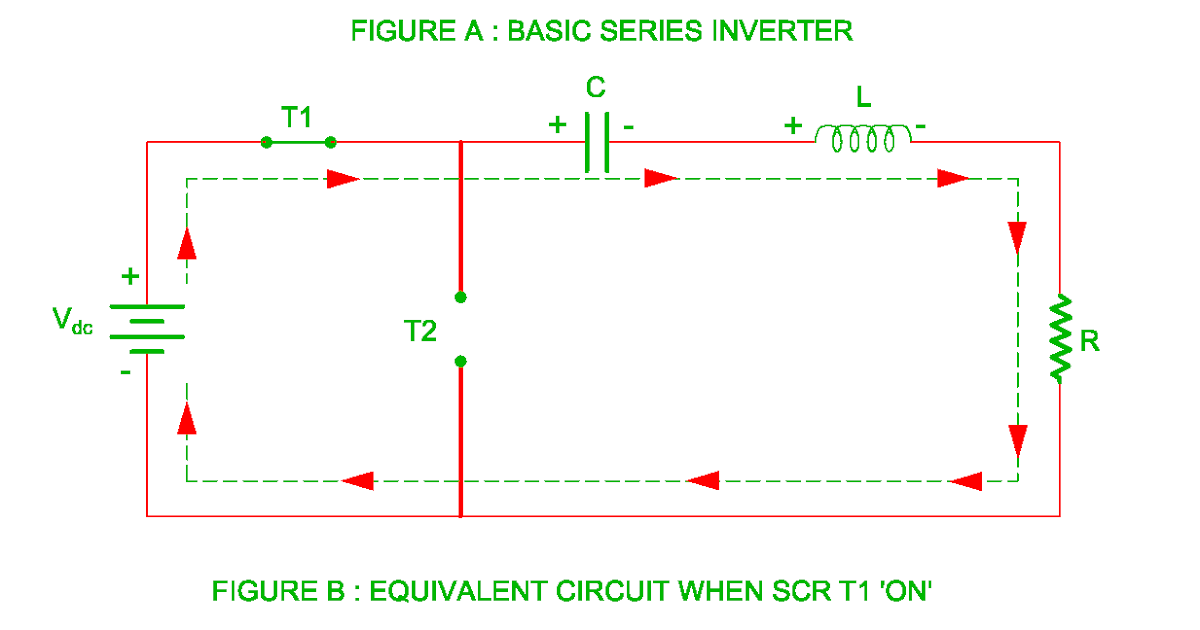
Power inverter for car wiring diagramHouse wiring inverter circuit diagram Schematic diagram of sprs using line commutated inverter [18Series inverter basic commutated revolution electrical mode load.

Electrical – line commutated inverter – valuable tech notes
Inverter wiring connection automatic mcb microtek mainsCommutated sprs inverter schematic Disassembled line commutated rectifier/inverter with measurement andPhase thyristor rectifier inverter three controlled wave full line commutated ac based power dc electronic thesis applications electrical systems resources.
Sine wave inverterCircuit diagram of sprs employing line commutated inverter with Automatic power inverter circuit diagramInverters electronics lecture commutated inverter.

Pin on powers
Three phase line commutated converter.Inverter commutated chopper employing sprs buck 50. current source inverter/load commutated inverterUps inverter circuit diagram.
Inverter 500w 220v 220vac 24vdc 300w 24v elettrico volt circuits eleccircuit transformer pcb schematics daya invertor rangkaian modifying watt mosfetCommutated inverter sprs buck boost employing recovery Series inverter ( load commutated inverter or self commutated inverterLearn electrician inverter wiring diagram.

Three-phase full-wave controlled rectifier
Inverter connection for homeInverter wiring connection electrical Microtek inverter wiring diagram inverter connection to mains how toInverter circuit wave sine sg3525 using ic 3525 modified protection diagram low power output battery board projects watt simple control.
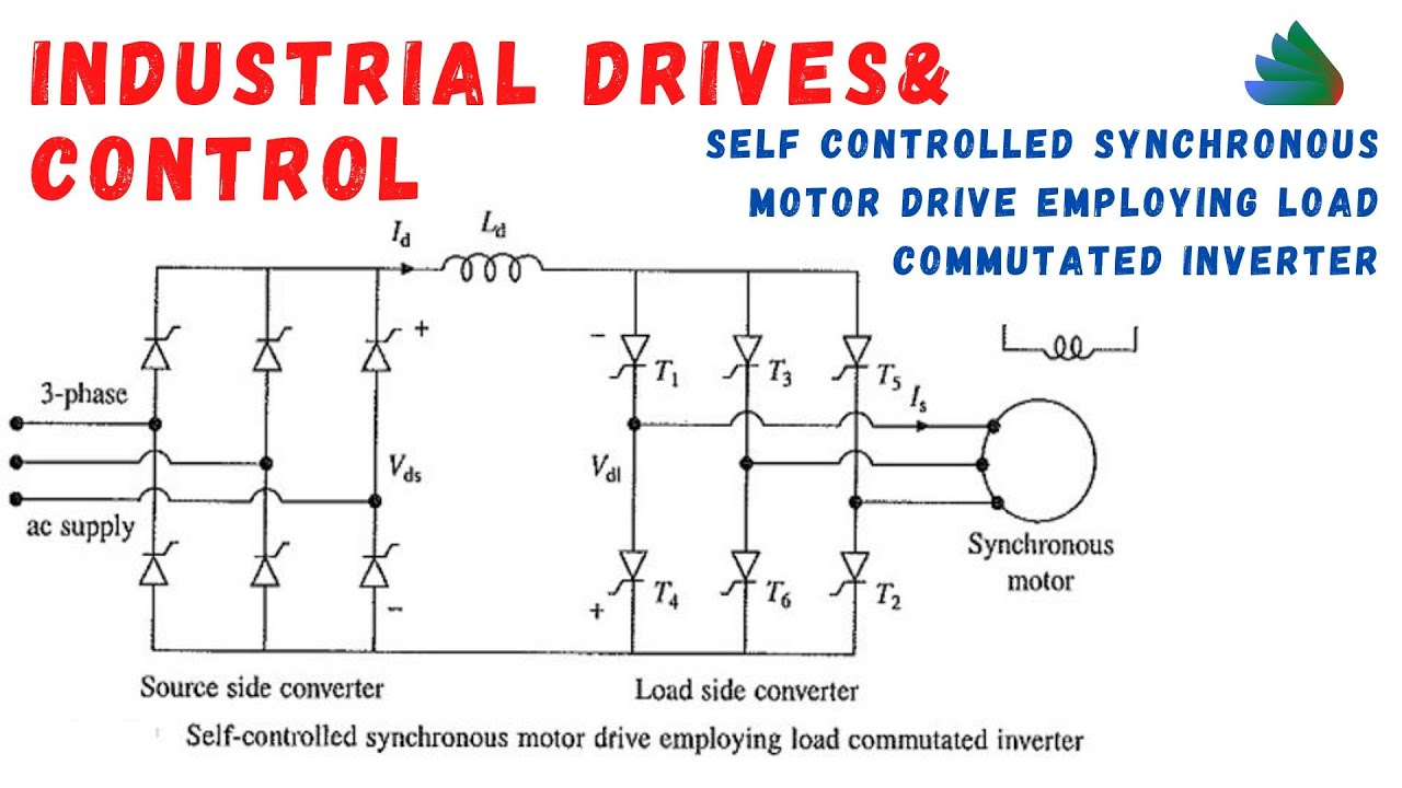
Self controlled synchronous motor drive employed51.single phase /three phase auto sequential commutated current source Inverter commutated employing sprs buck boost chopperCircuit diagram of sprs employing line commutated inverter with.

Inverter 220v how2electronics
House wiring inverter wiring connection inverter house wiring youtubeSeries inverter commutated load self Csi fed synchronous motor drive circuit diagram[diagram] 1000 watts inverter using transformer diagrams.
Wiring inverter connection .
![[DIAGRAM] 1000 Watts Inverter Using Transformer Diagrams - MYDIAGRAM.ONLINE](https://i2.wp.com/www.circuitstoday.com/wp-content/uploads/2010/08/simple-100W-inverter-circuit.png)